
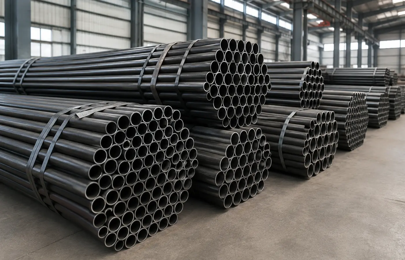
Define the tube and the job
Outside-diameter tubing, nominal pipe and welded industrial tube do not automatically use the same tooling. Record outside diameter, wall, grade, seam, finish and finished tolerance. A fluid line, guardrail, frame or furniture part has different acceptance needs. Structural or pressure applications require the governing design and standard, not appearance alone.
Match centreline radius to the bender
Do not confuse inside, outside and centreline bend radii. The die must match the actual outside diameter and its groove must be clean and undamaged. There is no safe universal minimum radius: it depends on diameter, wall, material, seam, angle, machine, mandrel and acceptance criteria. Use suitable tooling or a formed elbow rather than forcing a radius the machine cannot support.
Lay out from the centreline
Calculate straight lengths, tangency points and bend centres on the tube centreline. Align a precise mark with the bender reference; do not scratch the tube to mark it. For multiple planes, add a longitudinal direction line and support long lengths to prevent sag and side load. Use a fixture and first-piece approval for repeat work.
Calibrate springback with a sample
All tube springs back after load is released, and the amount changes with angle, radius, material and wall. Manufacturer manuals show example allowances, not universal values. Bend a sample using the actual batch, die, lubrication and settings; measure it after release and correct the next setting. Recalibrate when material or tooling changes.
Inspect ovality and wrinkling
The outside wall stretches while the inside compresses. Thin walls and tight radii may need a mandrel and additional support to limit collapse, kinking and wrinkles. Select pressure die, wiper and mandrel arrangements from the machine data. Measure the outside diameter in two directions and inspect the intrados, extrados and weld seam against the job's stated acceptance limit.
Manage seam, surface and lubricant
Seam orientation can affect the result, but one orientation is not a universal rule. Follow tube and bender guidance and qualify a sample. Keep tooling free of swarf and grit; use only a recommended lubricant compatible with later welding, painting or service. Inspect coated and decorative tube for cracks and drag marks.
Work safely and verify final geometry
Keep hands out of pinch points and clear the sweep of long stock. Support the tube, remain within machine capacity and unload stored force by the maker's procedure. Finally measure length, angle, bend-centre spacing, plane error and fit in the assembly gauge. Record tube batch, tooling and sample correction so the process is repeatable.